The differential configuration is rarely if ever talked about, even though it offers several valuable advantages over the non-inverting and inverting circuits discussed in the previous two posts. We use differential circuit design in our LM3886 boards.

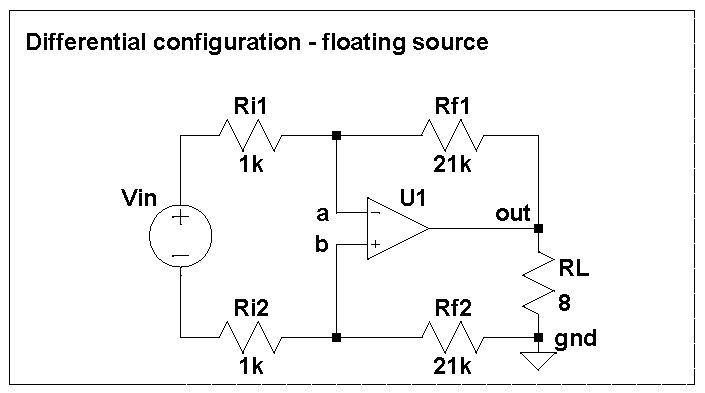
In this configuration, the opamp U1 (such as an LM3886) drives its output so as to minimize the voltage between points a and b in the feedback network, which leads to the following equality:
Vin / (Ri1 + Ri2) = V(out) / (Rf1 + Rf2)
Unlike the non-inverting or inverting, the differential configuration requires no shared reference point (a.k.a. "ground") between the source and the load. The correct feedback action is based on the voltage between the left ends of Ri1 and Ri2 for the source and between the right ends of Rf1 and Rf2 for the load and needs no common reference. Of course, the bottom end of the load needs to be connected to the power ground, but the input can be either left floating or grounded at either end.
This is a true differential input, and if you choose Ri1 = Ri2 and Rf1 = Rf2, it is balanced, too. One advantage of the balanced differential input is that ground loops do not affect its performance. Since the input is floating, any voltage between the signal source ground and power ground is common mode for the opamp and will be attenuated by the common mode rejection ration (CMRR). For the LM3886, the minimum CMRR is 85dB, although in practice it will be limited by the matching of the four resistors (see the schematic above).
Another advantage is that that both inputs of the opamp at at the same potential, so the ill effects of input currents cancel. This eliminates one source of distortion that is present in the non-inverting configuration.
The input impedance depends on how you connect the input. The differential impedance for the floating source is only twice that for the inverting amplifier, but if you ground (that is, connect to your signal source's local reference point aka "ground") the inverting input, the impedance for the non-inverting one becomes a healthy 22 kOhm.
As in the inverting configuration, the inverting input needs to be either driven by a low impedance source or grounded locally to keep the gain of the amplifier above 10 and prevent oscillations.